Author Topic: "Splitting The Cases" Time To Build!  (Read 38224 times)

0 Members and 1 Guest are viewing this topic.

ace.cafe

  • Grand Gearhead
  • *****
  • Posts: 14,457
  • Karma: 1
  • World leaders in performance/racing Bullets
Reply #15 on: May 22, 2014, 06:11:50 pm
That's pretty trued-up.
The drive side is often more out than the timing side because of the length.
I'd be inclined to leave it right there, unless you have a lot more time and patience with it, and it might not ever get any better than that.
Home of the Fireball 535 !


cafeman

  • Grand Gearhead
  • *****
  • Posts: 567
  • Karma: 0
Reply #16 on: May 22, 2014, 08:15:17 pm
That's pretty trued-up.
The drive side is often more out than the timing side because of the length.
I'd be inclined to leave it right there, unless you have a lot more time and patience with it, and it might not ever get any better than that.
.            Wish I could leave it but that rod is outta there soon. The pic is the crank fresh from the engine yet to be disassembled. After reading about how bad they can be it was surprising. Hopefully my crankpin is OK, as my plan is to press the crankpin from the drive side wheel, leaving the pin in the timing side wheel, as well as leaving both shafts in. Just thoroughly clean passages and trap etc......


ace.cafe

  • Grand Gearhead
  • *****
  • Posts: 14,457
  • Karma: 1
  • World leaders in performance/racing Bullets
Reply #17 on: May 22, 2014, 08:23:11 pm
Okay.
Very important to press the crankpin thru the flywheel eye perfectly straight. If it gets cocked at all during the pressing operation, it will broach material out of the flywheel eye, and the eye will no longer be round, and it will lose the tight interference fit, and will be troublesome later.

Press it home straight and true, Grasshopper!
 ;D
Home of the Fireball 535 !


cafeman

  • Grand Gearhead
  • *****
  • Posts: 567
  • Karma: 0
Reply #18 on: May 22, 2014, 08:48:04 pm
Yes sir!  If I can get away with it (one side) I figure leave well enough alone;)


cafeman

  • Grand Gearhead
  • *****
  • Posts: 567
  • Karma: 0
Reply #19 on: May 27, 2014, 02:30:03 am
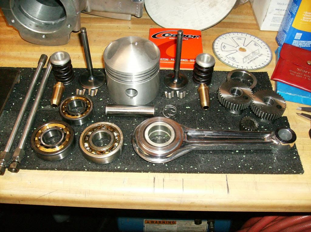
Parts are streaming in by the day, got things narrowed down and I believe I have a plan of attack. In no particular order: Looking like re-phasing the stock cams (thanks for Ace's work) my lift measures .308 on both lobes w/possible advanced? 3-way timing pinion (will check cam timing naturally beforehand) a Robbins .040 over 9:1 piston (piston weight 401g/ pin weight 103g) on a fully polished HDA alloy rod (332g) pumping in a 500cc alloy barrel (I want a barrel I can do re-bores if needed so will sacrifice the added cc benefits) carefully ported head (woked over throat, short side radius and valve guide boss streamlining) with Hitchcocks competition valve kit, stock steel rocker blocks machined to accept "modified" Samrat rocker arms, blocks will be raised .250 via plates which combined with the rockers actual ratio measurements, should yield about a 1.313:1 ratio for a tick over .400 lift and will utilize Hitchcocks 6mm longer alloy pushrods that will basically keep the same geometry from the lifters to the rocker pushrod ends. No pushrod clearance issues with the passages in cylinder or head. Essentially the valve side of the rocker arm will just be longer, have longer reach of an additional 5/16" (.3125) based on my figures (the existing rockers are not exactly 1:1, closer to .980 on the valve side, exact figures yet to be determined) FAG X-lite bearings, existing hi volume oil pumps, 1 3/4 sweptback exhaust w/Goldstar Silencer, Mikuni 34mm VM carb and for now the reliable points ignition. Really wanted to go with the coated ligtweight Ace piston, Carillo rod w/bronze bush and really like the rockers offered but funds just aren't there :'( 
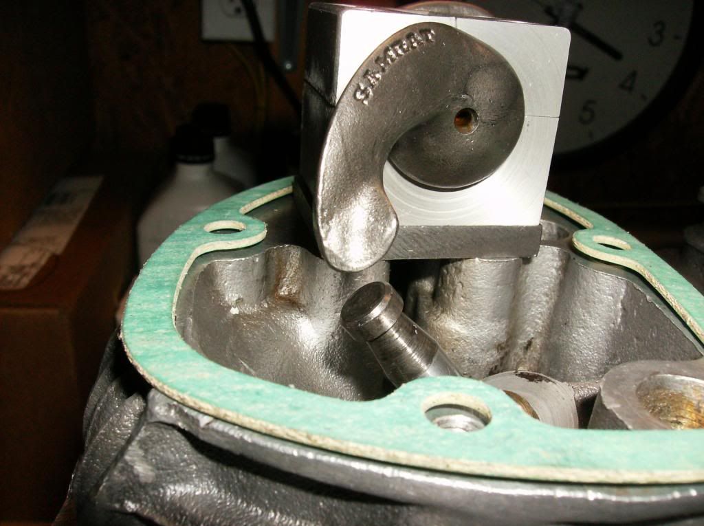
Here's a few shots with the rocker blocks in preliminary stage mock-up (soft alloy Samrat blocks will not be used) yet to machine steel blocks, brazed/welded custom ground rocker arm tips etc. Just what I've gathered so far, just for the sake of anyone interested in what others are doing ......nothing ground breaking, or new, just trying to build an engine that will handle speeds up to 80mph or so with the capability of short blasts beyond that, and doing things on what has turned out to be a shoe string budget  ::)

« Last Edit: June 19, 2014, 10:49:37 am by cafeman »


cafeman

  • Grand Gearhead
  • *****
  • Posts: 567
  • Karma: 0
Reply #20 on: June 08, 2014, 07:45:50 pm
So I got around to separating the crank, checking things over and then installing the new bush and English alloy rod. Ended up getting the 12 ton hydraulic press (a long time coming and invaluable) and a 2lb brass hammer from good old Harbor Freight. Had to spend a little time setting up the press so all is square, but in the end it works a charm. After taking measurements at four points around the crank for reference, it came apart easily, using an impact wrench to remove the crank pin nut, and then pressed out the crank pin from the drive side wheel, leaving drive and timing shafts in and crank pin in the timing side wheel. The original white metal bush was in excellent condition as was the rods fixed bush and crankpin. Not bad after what I subjected the engine to......Cleaned up everything, checked clearances of the new parts, coated the bearing surfaces with moly assembly lube and pressed it back together to an initial stage where I had about 0.020 on the drive and 0.005 on the timing. Then proceeded to whittle it down in stages as I got the run-out closer as well as pressing together and torqueing the crankpin nut a little at a time and checking as I went along. In the end I got the web distances measuring essentially the same as prior to disassembly. I got even better run-out readings than what the original setup was before disassembly. Drive side came out to 0.001 and the timing side came out to 0.0005. It took about 5 separate whack/measure/press/torque/measure to get it to those readings. Less than 30 minutes total. Very smooth and easy I have to say, and I am extremely happy. Now the alloy cylinder, 9:1 piston and ported head are off to the machine shop for boring/honing to .005/.0055 clearance, and a nice valve job followed by some finish porting (to blend in the new exhaust seat as well as open up the intake seat to suit the bigger valve being installed) when I get things back.
One note, I'm using Hitchcocks oversized bronze valve guides, and the shoulder as it rests on the head is taller than the standard valve guide or for that matter the standard Hitchcock guide that comes in their kit. It will need to be turned down so the lower valve spring collar will seat on the head. Something you do-it-yourselfers may want to know about ahead of time if considering the oversized guides (I can deal with the extra machining to fit as it's not a big issue really)


8)


Bullet Whisperer

  • Grand Gearhead
  • *****
  • Posts: 1,133
  • Karma: 1
Reply #21 on: June 08, 2014, 08:43:52 pm
I keep my valve spring seats off the machined face on the cylinder head and sometimes fit shims between the guides and the spring seats - it keeps weight on the valve guides and allows the valves to rotate if they want to, also you can optmise the fitted length, preload and full lift load of the valve springs in this way  ;)
 The job's looking good there  8)
 B.W.


cafeman

  • Grand Gearhead
  • *****
  • Posts: 567
  • Karma: 0
Reply #22 on: June 08, 2014, 08:56:14 pm
And here's some pics of the porting I've done, utilizing a Makita electric die grinder and a Dremel both with various stones, cutters etc for fine detail work.......Areas with most attention were the guide bosses and surrounding port roof area, short side radius, bowl and throat blending. Tapered the intake a wee bit to suit the 34mm Mikuni and alloy adapter, otherwise left runners alone.  40 grit finish in the intake for better atomization etc. The basics per my experiences, studies and readings here, elsewhere, with a heavy influence and study of David Vizard theory going back some 30 years with engines.  Fun stuff 8)


cafeman

  • Grand Gearhead
  • *****
  • Posts: 567
  • Karma: 0
Reply #23 on: June 08, 2014, 08:58:16 pm
I keep my valve spring seats off the machined face on the cylinder head and sometimes fit shims between the guides and the spring seats - it keeps weight on the valve guides and allows the valves to rotate if they want to, also you can optmise the fitted length, preload and full lift load of the valve springs in this way  ;)
 The job's looking good there  8)
 B.W.

Hmmm, I will run that by the machinist. Makes sense. Thanks! ;)


ERC

  • Grand Gearhead
  • *****
  • Posts: 1,810
  • Karma: 0
Reply #24 on: June 08, 2014, 10:56:32 pm
It's looking really nice Cafe.   ERC
2-57 Apaches, 2-57 Trailblazers, 60 Chief, 65 Interceptor, 2004 Bullet, 612 Bullet chopped.


cafeman

  • Grand Gearhead
  • *****
  • Posts: 567
  • Karma: 0
Reply #25 on: June 09, 2014, 05:06:30 pm
Installed the bearings in the cases. Heated each case (one at a time) in the oven set at 300 degrees for about 10 minutes each (they didn't actually reach that temp) and stuck the bearings in the freezer. Then popped them in their bores till fully seated, gently tapped and drifted to make sure they were parallel with the flats for sure, as well as checked the ball bearing to ensure it too was parallel with a dial caliper.  Installing crank and bolting up the cases, checking everything for flat cylinder base, smooth rotation, ensure there will be no leaks etc is next.  :)
« Last Edit: June 09, 2014, 05:46:18 pm by cafeman »


cafeman

  • Grand Gearhead
  • *****
  • Posts: 567
  • Karma: 0
Reply #26 on: June 10, 2014, 04:45:45 pm
Crank installed in the left case, used what I had on hand along with the sprocket, rotor and the nut to draw the crank into position as described in the manual. Went in smoothly. Checked crank to ensure it is centered, rod small end lays dead center with the case mating surface, and I also checked the crank webs being centered with a straight edge and caliper at various points. All good, I then loose fit the right case with no bolts and rotated the crank checking for any movement of the right case. No traces of any movement. After dry fit (with gasket) joining the cases (prior to sealant) I will check for smooth rotation and may even double check the shafts run-out just to be certain that nothing went afoul during all this. New grub screw installed, along with thrust washers and inner bearing races which I heated and they dropped right on 8)


cafeman

  • Grand Gearhead
  • *****
  • Posts: 567
  • Karma: 0
Reply #27 on: June 17, 2014, 10:26:33 pm
Cases now assembled. Checked run-out and end float, seals installed with timing seal spring side out. Mating surfaces cleaned with acetone, light coating with Permatex High Tack, and gasket installed. Studs coated with light coating of anti-sieze just because.......All snugged up. Run-out on drive shaft changed just a smidge to .0015 from .001, likely setup differences as there was no beating or banging going on, timing side was fun improvising a mount as best I could so as to get a repeatable measurement which was .0005....checked the end float (before fitting sprocket, spacer and rotor which reduces it to zero)  even though I couldn't find specs or mention anywhere. Rotates nice and smooth! Will fill oil tank with some light fluid and check for leaks after sitting for awhile, then sump and repeat just to be sure. More to follow 8)


ace.cafe

  • Grand Gearhead
  • *****
  • Posts: 14,457
  • Karma: 1
  • World leaders in performance/racing Bullets
Reply #28 on: June 17, 2014, 11:58:02 pm
Looks good.
Nice and clean!
Home of the Fireball 535 !


cafeman

  • Grand Gearhead
  • *****
  • Posts: 567
  • Karma: 0
Reply #29 on: June 18, 2014, 03:24:22 pm
Most assembly will be stalled until I get the cylinder and head back, machinist is backlogged with engine work. Looking like end of the month.  I will be gathering the 4-speed and primary electric to kick parts. Close ratio gear-set, rebuild kit, and sealed bearings. I'll probably reuse the crank sprocket after lopping off the ES gear as Chumma mentioned and source a KS inner, and source the hardware elsewhere if needed. Should save quite a bit of money that way and be the same.
Meanwhile, I am working on the rockers and blocks to hopefully end up with the higher ratio I'm after. Lots of thinking, tinkering, measuring, and more thinking. Got the .250 block plates sorted that will lift the steel blocks up, deciding on what longer pushrods to use in order to keep the rockers positioned properly on the pushrod side. I already have heli-coils in the head and I will use the same length studs, but having raised the blocks the thread engagement into the head is reduced. So I will take off a little on the tops so there is more thread engaged in the head. Plenty of meat for strength between the cut and rocker bore so I think that will be ok. Also reduced the width of the block so the Samrat rockers fit. Mockup looks good so far. Rocker Covers clear so I won't need to fab spacers which is nice. Obviously the biggest issue, and last remaining is lengthening the valve side arms to get the increased ratio.  Any welding/brazing will all have to be done by my machinist. I'll likely finish the ends/pads myself for contact/sweep etc. I'll probably do some wood or clay modeling to see if any of it would work and be strong enough. Just a reminder, all this is mock-up quality, nothing final, and may be aborted in the end! Just seeing where all this shed time will take things! :o


« Last Edit: June 19, 2014, 12:10:13 pm by cafeman »