Author Topic: Indian Chief build, looking for Information  (Read 102474 times)

0 Members and 1 Guest are viewing this topic.

grumbern

  • Grand Gearhead
  • *****
  • Posts: 667
  • Karma: 0
Reply #285 on: February 23, 2019, 08:57:19 am
Well, I just saw I haven't written a lot lately! So I'll skipp the speech and let the pictures do most of the talking ;)

Made a bracket for the ignition switch, but screwed up with the measurement somehow, so had to cut about 1/2" and weld it. Luckily it's not noticable :)


grumbern

  • Grand Gearhead
  • *****
  • Posts: 667
  • Karma: 0
Reply #286 on: February 23, 2019, 09:00:45 am
Also I got my hands on some silver couloured piping and finished the dip switch:


After searching and waiting for some round headed BA5 screws I could drill and tap the handlebars to mount the switch:


grumbern

  • Grand Gearhead
  • *****
  • Posts: 667
  • Karma: 0
Reply #287 on: February 23, 2019, 09:05:05 am
Another detail. At HMC they offered a 20% discount on reduced items, and I found a pair of "nos" General Electric spots:


And as one of the "old" ones was cracked anyway...


... and I also had to replace the supply cable, I went for these. Isn't that logo in the middle alone just gorgeous?!


grumbern

  • Grand Gearhead
  • *****
  • Posts: 667
  • Karma: 0
Reply #288 on: February 23, 2019, 09:11:02 am
Of course I didn't stop there.
After the ignition switch bracket was ready and painted, I could mount and connect the switch. I had to make a littlte jumper, as with the twins terminals 6 and 8 are connected, while 6 and 15 are with the singles (standard with RE switches, obviously). This is because of the emergency start function is a little different. The white cable goes at terminal 8 instead of 6, because my connectors are mirrored (my bad...), but wouldn't disturb anyone ;)


grumbern

  • Grand Gearhead
  • *****
  • Posts: 667
  • Karma: 0
Reply #289 on: February 23, 2019, 09:36:25 am
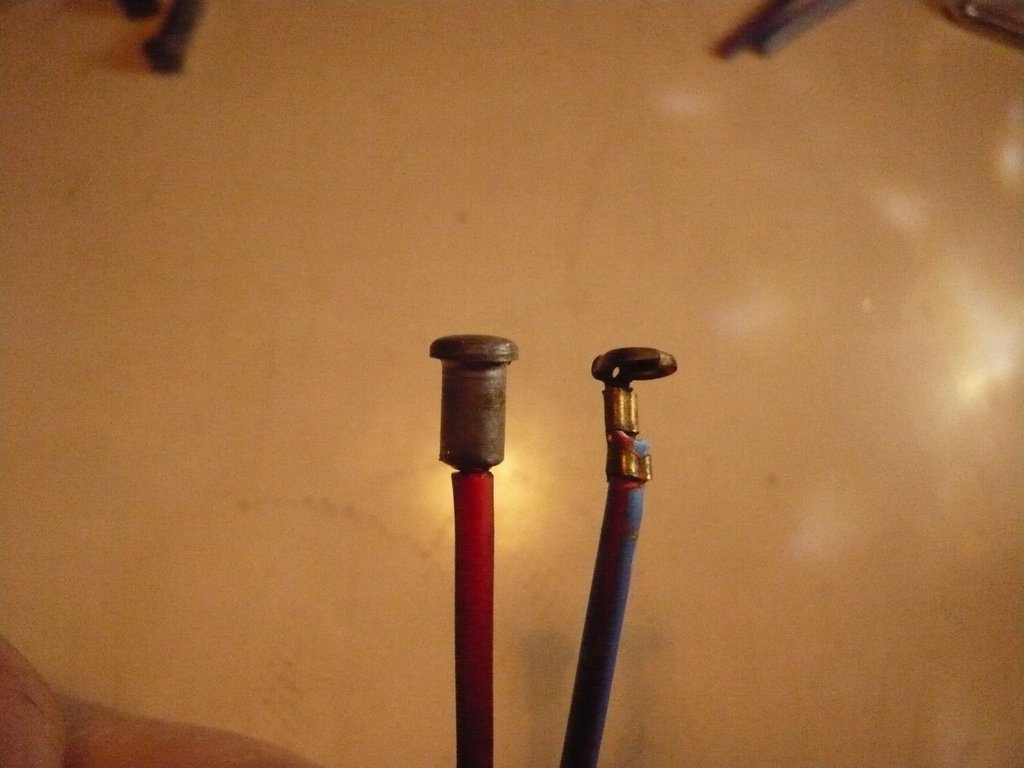
At the headlight they had cheap crimped contactors and a fixed ground wire. Also, the connectors didn't stay in the couplers, which is deadly at the headlight (up to 6A of current)! The colours didn't match too and all in all it was pretty shabby. Same for pilot and tail light, tough this was genuine Lucas (but they don't do it for me either).


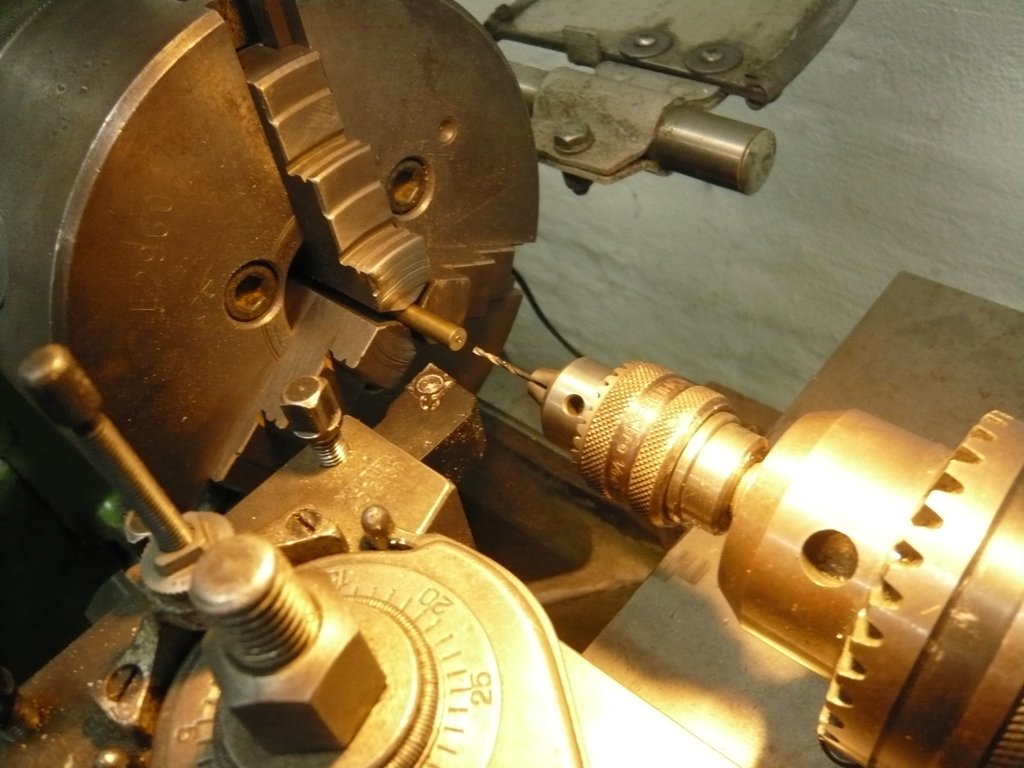
Luckily I had an old socket. The main contactors couldn't use as these were pressed on the wires, but the rest was good an so I got me some brass and started turning:
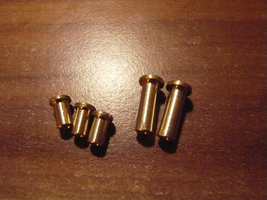
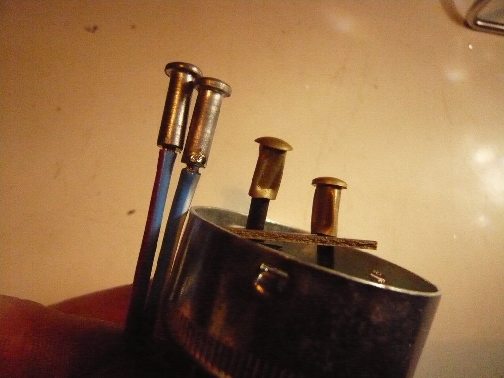


The result:


I wanted to galvanize the contactors, but the solution wasn't good anymore. After more than a day I quit it and just soldered them. Looks hideous, but at least theres some tin on them ;)


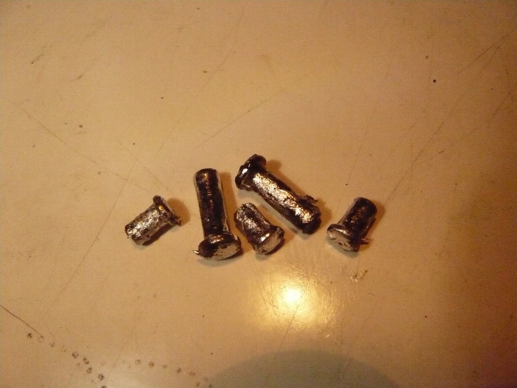
After that I heated them and removed all excess tin with a fine brass brush until there was only a thin layer left. The I prepaerd and soldered the correct wires.
Here's a comparison of the tail light contactors:


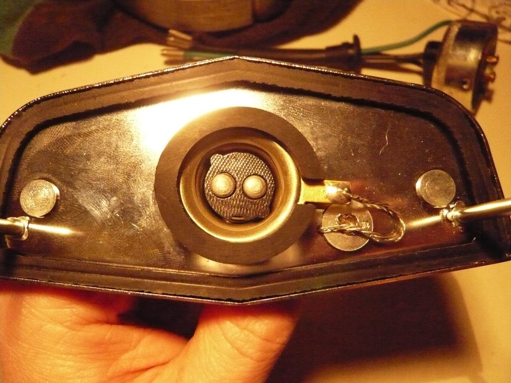
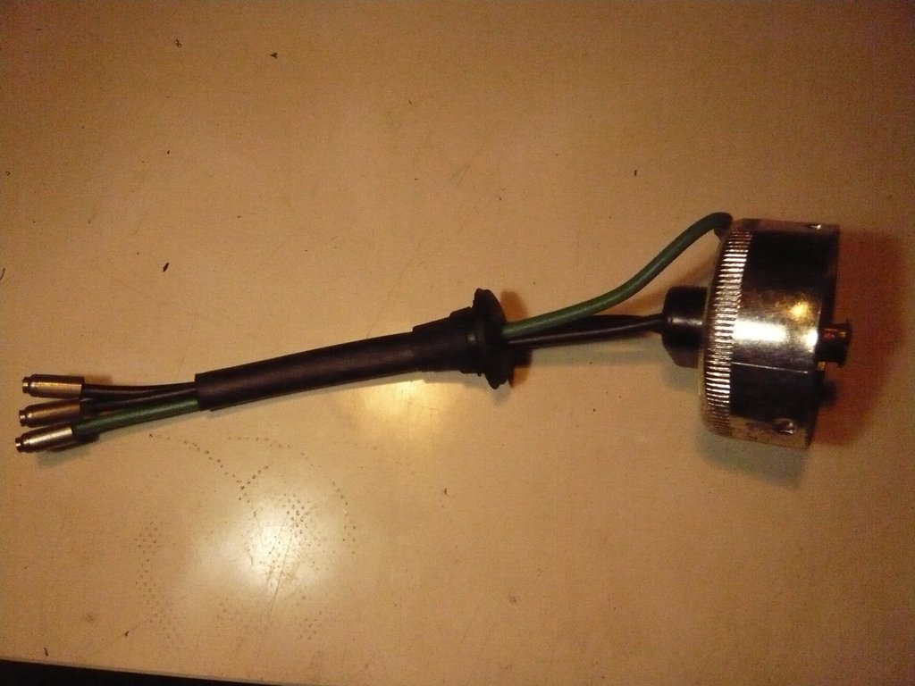
Same for the headlight:


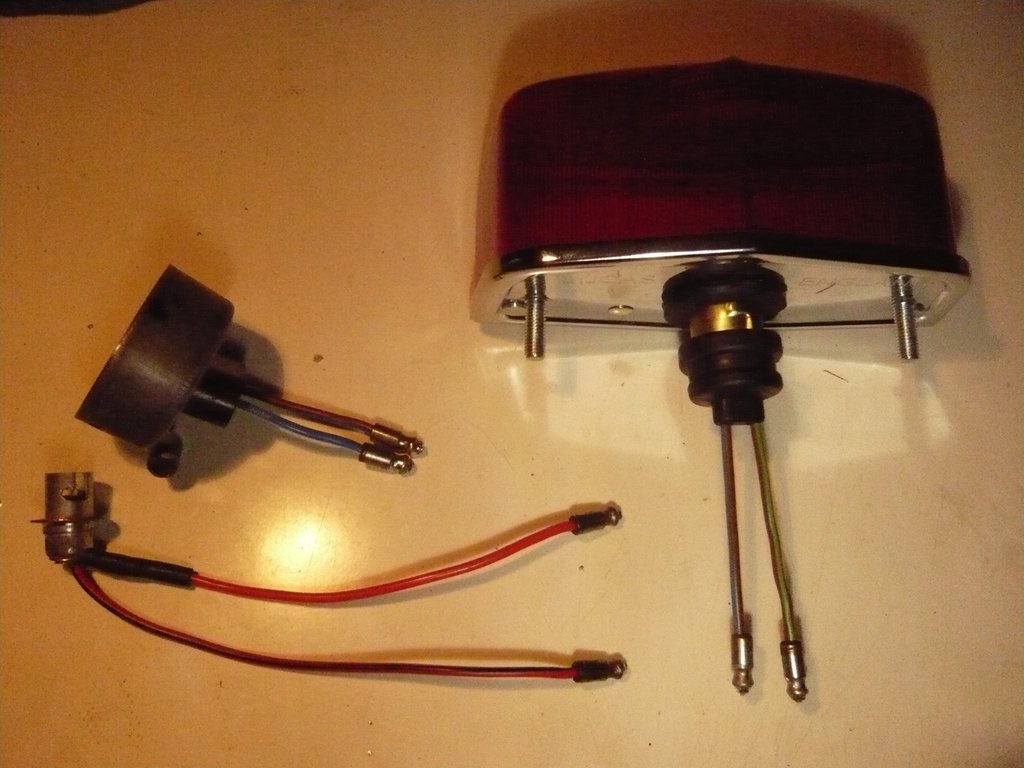
The "new" sockets, ready for assembly. Much better than before:


Yesterday I got some new tyres (3rd pair now :o) and hopefully these will finally fit. I went for the Avon Safety Milage II and heck, these look fantastic!
Until then...
Andreas


grumbern

  • Grand Gearhead
  • *****
  • Posts: 667
  • Karma: 0
Reply #290 on: February 23, 2019, 09:38:06 am
Oh, right: Can anyone tell me, how the wires were routed under the rear mudguard please?!

Also, how on earth is it possible, to mount the tail light? If the bracket is bolted to the mudguard and the cover screwed on, its impossible to reach die studs of the light. If the bracket and the light is mounted, you can't get the cover on there. If you assemble brackt, light and cover you can't reach the bolts to mount it all to the mudguard. So what am I missing?! ??? :o >:(
« Last Edit: February 23, 2019, 06:10:18 pm by grumbern »


Adrian II

  • Grand Gearhead
  • *****
  • Posts: 4,138
  • Karma: 1
  • Sharing my ignorance with anyone who needs it
Reply #291 on: February 24, 2019, 09:32:49 pm
Do you have any pictures to illustrate the tail light mounting problem, Andreas?

A.
Grumpy Brit still seeking 500 AVL Bullet perfection! Will let you know if I get anywhere near...


grumbern

  • Grand Gearhead
  • *****
  • Posts: 667
  • Karma: 0
Reply #292 on: February 24, 2019, 09:49:23 pm
See attached two photos. Both aren't mine, I hope that's ok?!
You can pretty much see how the light and bracket are mounted to the mudguard, but the tricky part is that cover! This is slung below the two ears that are foldes to the front, right under the light's mounting studs.


Adrian II

  • Grand Gearhead
  • *****
  • Posts: 4,138
  • Karma: 1
  • Sharing my ignorance with anyone who needs it
Reply #293 on: February 24, 2019, 10:35:46 pm
What sort of screw is used in the top picture on the top of the mounting bracket in your first picture? Will you be using something similar?

I would be tempted, if a pan-head screw is being used, to use a couple of blobs of spot weld to hold the screw in position, THEN fit the
guard and the 564 rear lamp back plate, using a small box spanner for the 2BA nuts, THEN fit the whole assembly into the rear mudguard.

Not being familiar with the Chief rear mudguard I could only hazard a guess about the cable routing, will you be adding a separate earth wire to the stop and tail lamp wires? Assuming adhesive plastic cable clips are a huge no-no for the philosophy of this build, how about metal "P" clips? I'm guessing the wires are run through cable sleeving.

https://www.ebay.co.uk/itm/SOLID-BRASS-5MM-P-CLIPS-CABLE-WIRING-PIPE-BRAND-NEW-PK-25/250694829849?hash=item3a5e938719:g:~SQAAMXQgb1RQMix

A.
Grumpy Brit still seeking 500 AVL Bullet perfection! Will let you know if I get anywhere near...


Adrian II

  • Grand Gearhead
  • *****
  • Posts: 4,138
  • Karma: 1
  • Sharing my ignorance with anyone who needs it
Reply #294 on: February 24, 2019, 10:40:04 pm
Or these:

https://www.ebay.co.uk/ item 311795139359


A.
Grumpy Brit still seeking 500 AVL Bullet perfection! Will let you know if I get anywhere near...


grumbern

  • Grand Gearhead
  • *****
  • Posts: 667
  • Karma: 0
Reply #295 on: February 25, 2019, 04:22:03 pm
Hi Adrian,
mine is mounted just like this in the picture. I also thought about mounting the whole assembly like you suggested, but they would have done that different, wouldn't they?

I routed the wires between the mudguard and it's bridges and it stays pretty much put. I only hope it will do so with the bike in action ;)
After all, I guess the old Brit's didn't care a lot about how they put their wires on their bikes, as long as they were ther?! ;D

The wheels and tyres are at the garage and will be ready to collect tomorrow.
If anyone knows about the above points, please let me know!
So long,
Andreas


ERC

  • Grand Gearhead
  • *****
  • Posts: 1,810
  • Karma: 0
Reply #296 on: February 27, 2019, 12:31:57 am
They used cable clips #27685 to fasten the wires to the fender.  ERC
2-57 Apaches, 2-57 Trailblazers, 60 Chief, 65 Interceptor, 2004 Bullet, 612 Bullet chopped.


grumbern

  • Grand Gearhead
  • *****
  • Posts: 667
  • Karma: 0
Reply #297 on: February 27, 2019, 07:39:00 pm
Picked up my wheels yesterday:


Well? What a sight, amazing! ;D
These tyres are so damn high they even beat the much wider Continentals and certainly the look the part!

Also I prepared the speedo drive housing for polishing:


So long,
Andreas


Adrian II

  • Grand Gearhead
  • *****
  • Posts: 4,138
  • Karma: 1
  • Sharing my ignorance with anyone who needs it
Reply #298 on: February 27, 2019, 09:05:01 pm
On the front wheel that higher profile front tyre/tire will look better with the mudguard/fender!

A.
Grumpy Brit still seeking 500 AVL Bullet perfection! Will let you know if I get anywhere near...


grumbern

  • Grand Gearhead
  • *****
  • Posts: 667
  • Karma: 0
Reply #299 on: February 28, 2019, 04:09:20 pm
Definitely! At the moment I can't mount it yet, as I have to wait for the speedo drive to be ready, so I can first set the rear wheel in place. otherwise the bike will fall ;)