Author Topic: Proper side stand bypass & relays  (Read 4589 times)

0 Members and 1 Guest are viewing this topic.

dginfw

  • Grand Gearhead
  • *****
  • Posts: 880
  • Karma: 0
on: July 13, 2014, 09:30:42 pm
I’ve been wanting to do a proper bypass on the side stand switch (that will allow you to use the side stand with the engine running IN NEUTRAL, but not in gear) for some time now, but we are rapidly approaching triple-digit heat here in North Texas, and I’m getting lazy in my middle age, so bear with me….
I will post details/instructions in as few sections as I can. I do feel that I should write up a short primer on relays for those that are unfamiliar with them. That will be the first part.
Anyway, as with any modifications, disclaimers are needed:
-do this at your own risk. If you are not comfortable cutting and splicing wiring you might want to hold off on this one.  You will need basic wring tools, like wire cutters, wire strippers, and some means of connecting wires like crimpers or a soldering iron.  If you can’t make a good quality connection, don’t do it.  Simply twisting wires together and wrapping with tape is NOT a good connection.  It will fail.  And most of all do not use the ‘wire nuts’ that are used in home electrical wiring. They are not designed for an environment that vibrates, shakes, and moves like a vehicle does.

Relay basics:
A relay is nothing more than an electro-mechanical switch.  Inside the relay is a coil, that when energized, becomes an electromagnet. This magnet pulls a metal lever from one electrical contact position to another.  That’s it…no magic. No mystery.  When you hear a relay ‘click’ you are hearing the contact lever moving from one position and clicking when it contacts the next one.
While there are many different types of relays –some with multiple switches- for our purposes we will work with a SPDT (single pole, double throw) type. These are the most common.
They will typically look like this, but some may not have the built in bracket on the body.

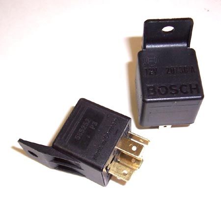
There are many brands available. Bosch has been regarded as the industry standard for years, but I believe they are now branded as ‘Tyco’.  Another good brand is Potter& Brumfield.
The bottom of the relay is where the ‘contacts’ are located. They are the metal prongs that stick out.  The layout of these is standardized and labeled on most SPDT relays. There are five contacts and they are numbered: 85, 86, 87, 87A, and 30.

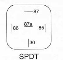
85 and 86 are the contacts for the coil. This is what powers up the electromagnet and makes the click.  Putting 12V positive on one (85) and 12V ground on the other(86) is all that is needed to power up the relay…and the amount of current it takes is tiny -in the milliamps. This is how some motorcycles can have a tiny micro switch on the handlebars controlling things that normally require large amounts of current.  All the switch has to do is power the relay, and the relay powers the light or the starter.  I am a firm believer in using relays to control current instead of the switches themselves. While both (switches and relays) can fail, it is easier to unplug a relay and plug in a new one than it is to rewire a wire harness or replace a switch because they couldn’t handle the current flow.
The other three contacts :  30, 87, and 87A and the ones that handle the electrical flow and do the switching.  The easiest way to visualize it is think of a fork in a road. The coil is the device that directs the flow from one side to the other

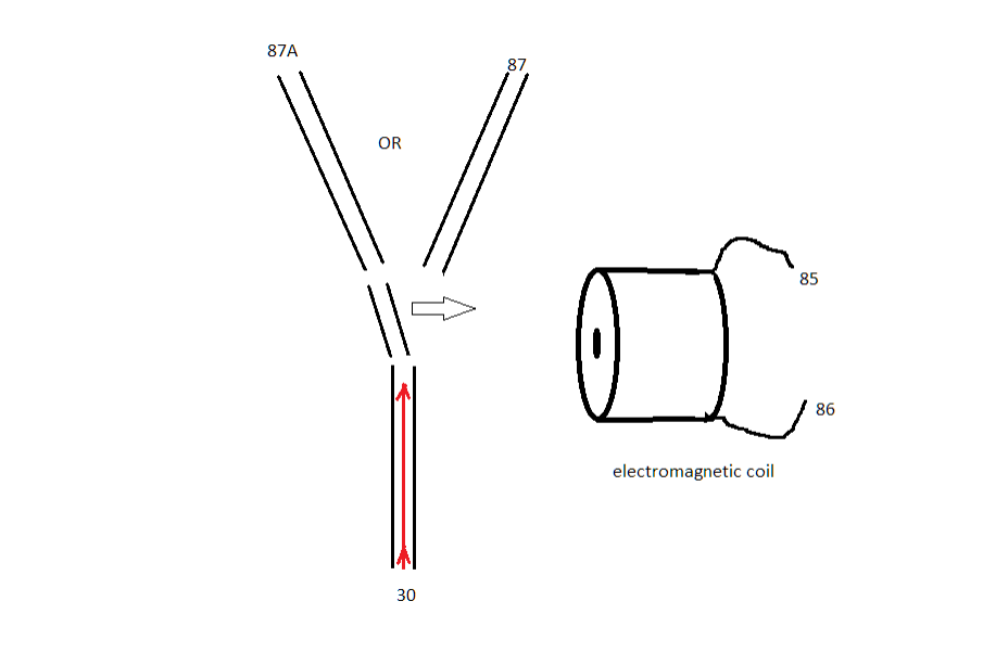
Normally (when the relay in not energized) the contacts of 30 and 87a are connected. When the coil gets power, the magnet pulls the switch from 87a to 87.  It is easier to understand the relay when you think of the coil contacts (85, 86) as just being the on/off switch for the relay. That way you only deal with three contacts:   The one at the bottom (30) is the common contact amd the other two (87, 87a) are where 30 is connected to when the relay is either on or off.

The side stand switch

On the recent UCE bikes the side stand switch must be up for the engine to start and run.  This is fine sometimes but can be a pain at other times. Some people simply unplug the switch harness, but that leaves the possibility of riding off with the stand in the down position, which could be a problem and cause a wreck when you lean into a left turn. The solution is to allow the bike to run with the stand down BUT ONLY IN NEUTRAL.  Most modern bikes operate this way, but the engineers at Royal Enfield overlooked this. Maybe they were concerned with prolonged idling on the side stand leading to oil starvation at the oil pump…I don’t know.  If someone out there more familiar with where the oil pump pickup is on the UCE motors can help out that would be great.  But I digress…
Anyway, we have to trick the bike into thinking the side stand is up when it’s not,  but only when the bike is in neutral.  This is where knowing how relays work comes in.  You see, the circuit for the side stand is open when the stand is up, and completed when it is down. Kinda like this:

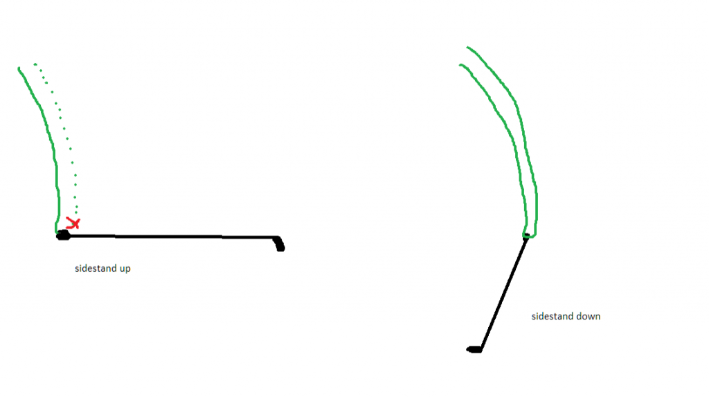
This is why unplugging the switch works; when it is unplugged, the bikes fuel cut off system never sees the completed circuit when the stand goes up. Even though the stand is down, the ‘brain’ of the system never sees the signal telling it that the stand is down. So how do we duplicate this?  We use a relay to open the circuit so that the bike does not see the ‘stand is down’ signal when certain conditions are met. What conditions would those be?....igniton switch on and bike in neutral.  Thankfully we have a wire coming out of the engine to tell us when the bike is neutral (that’s how the green light on the instrument cluster works) and those two conditions will be the triggers for the relay coil to energize. This way if the bike is running and on the side stand, and the rider puts it in gear without raising the side stand, the engine will die. When the neutral indicator goes out, the relay goes back to its default position and the bike operates as it normally does. When it’s in neutral, the relay is energized and it simulates the condition of disconnecting the side stand switch.  This way, if the relay ever fails, the modification will revert the wiring back to factory situation.  A ‘fail-safe’, if you will.

I will cover the actual install and bike wiring in the next section of this thread. Hopefully I get to it pretty quickly this week.
Dave in TX:   '01  W650- keeper
                    '12 C5 military -sold
                    '14 Continental GT-  sold
                    '06 Iron Barrel Bullet- Ace Clubman mods


ERC

  • Grand Gearhead
  • *****
  • Posts: 1,810
  • Karma: 0
Reply #1 on: July 13, 2014, 10:58:16 pm
I don't think you want to leave the engine running on the side stand. It's possible to suffer oil starvation with it on the side stand.  ERC
2-57 Apaches, 2-57 Trailblazers, 60 Chief, 65 Interceptor, 2004 Bullet, 612 Bullet chopped.


dginfw

  • Grand Gearhead
  • *****
  • Posts: 880
  • Karma: 0
Reply #2 on: July 13, 2014, 11:21:19 pm
I don't think you want to leave the engine running on the side stand. It's possible to suffer oil starvation with it on the side stand.  ERC
Thats what I was wondering. ...I know lots of people have disconnected their switch but I have not heard of any confirmation of oil starvation.  Hopefully we can get more input on this
Dave in TX:   '01  W650- keeper
                    '12 C5 military -sold
                    '14 Continental GT-  sold
                    '06 Iron Barrel Bullet- Ace Clubman mods


azcatfan

  • Grand Gearhead
  • *****
  • Posts: 525
  • Karma: 0
  • 2002 Bullet ES
Reply #3 on: July 13, 2014, 11:32:11 pm
I'd be too worried about it vibrating and falling leaving it run on the side stand a la Scottie's '58 Indian...  Getting rid of the switch though, because of how troublesome it can be, is worth it.
-2002 Bullet ES Up-Jetted with Ace Air Canister and punched HD Exhaust.

My MotoVlog Channel:  http://tinyurl.com/nnso3av


Arizoni

  • Grand Gearhead
  • *****
  • Posts: 7,412
  • Karma: 2
  • "But it's a dry heat here in Arizona
Reply #4 on: July 14, 2014, 02:49:46 am
dginfw
Well written.  Many thanks. :)

I've run the engine at idle speed with the sidestand down many times.  No problem whatsoever.

Usually this has been when I've forgotten to open the back yard gate.  Riding around the corner of the house and WHOA!  Who forgot to  open the gate?  ::)

Anyway, lowering the sidestand while the engine is still running and opening the gate fixes the problem.

As for the oil pump pickup, it's under the cover on the bottom of the engine towards the right side.  Yes, the oil level will drop when the bike is placed on the sidestand but because the pickup is much closer to the center of the engine than the sight guage there is still enough oil to keep the pump from sucking air.

I don't recommend running the engine above an idle speed while the bike is resting on the sidestand though.  It probably wouldn't hurt it but why take the chance?
« Last Edit: July 14, 2014, 03:05:21 am by Arizoni »
Jim
2011 G5 Deluxe
1999 Miata 10th Anniversary


Bulletman

  • Grand Gearhead
  • *****
  • Posts: 773
  • Karma: 0
  • 2011 - C5 Classic Black
Reply #5 on: July 14, 2014, 07:22:46 am
Dgibfw,
Excellent writing and explanation of relays, I feel like I'm in a class that I enjoy going to, and I'm looking forward to the next session...  :D
"A Blast from my Past"
Black C5 2011


dginfw

  • Grand Gearhead
  • *****
  • Posts: 880
  • Karma: 0
Reply #6 on: July 25, 2014, 05:35:22 am
Sorry for the delay; here's the second part.


Using the relay to interrupt the side-stand circuit:
So from our previous discussion, we know that the side-stand circuit kills the motor when the switch is in the down position. The best analogy would be the old 'one-wire' ignition killswitch on vintage bikes: when ground (negative earth) was applied to the wire, it killed the motor by killing the spark. Same principle... connection is made and the motor dies.

So to duplicate the sidestand being in the up position,(when it is really down) we must open the circuit back up. Lucky for us the "DT" part of a SPDT relay stands for 'double throw'.....it has two positions which provide an electrical path. One path for when the relay is NOT energized, and one for when it IS energized.  As in the 'fork in the road' picture above,  contacts 30 and 87A are connected when the relay is at rest. These are the two terminals we will use when we tap into the side-stand switch wire. This way under normal conditions (99.9 percent of the time) the relay is not energized.  When it IS energized, the electric 'gate' inside the relay is moved and the connection between 30 and 87A is broken, giving the electrical equivalence of the side-stand being in the up position.
   An added safety feature when wired this way is that if the relay fails to energize or fails for whatever reason the side-stand switch will act like it normally does from the factory. While it is possible for a relay to fail and stick open in the energized position it is not common. I have seen it happen before, usually when a relay was mounted improperly and the internal contacts rusted and locked in the 'on' position. Always mount relays with the electrical connections facing downward to keep water from entering the relay. This is why they have a mounting tab on top, opposite of the terminals.
  So to energize the relay's coils, we know we need both 12V positive (+) and 12v ground (-) applied to the relay's coil terminals 85 and 86. (Not on the same terminal, LOL)  We can get 12V positive from the bike's fusebox. Find a wire that powers up when the key is turned to the 'on' position.  Do not use the battery for 12v power because the battery is hot all the time. We want a wire that only goes hot when the bike is running.  The other side of the relay coil will get the 12v ground from the bikes neutral wire feed coming out of the top of the engine case just behind the starter

In that picture you can also see the red plug for the side stand switch. That is where we will get the wire (either one) for the terminals 87A and 30.  So when the ignition is ON and the bike is in neutral, the relay's coil will energize and open the circuit on the sidestand wire....and the bike will think the side stand went into the UP position. Not only will it start, but you will be able to put the sidestand down and hop off the bike and keep the engine running. (For extended running while parked, always use the center stand for safety's sake.)  This is why we want a 12v positive source that turns off with the key switch; if it stayed hot the relay would stay energized as long as the bike was in neutral. If you parked your bike and left it in neutral the relay would drain the battery eventually. So we only want the relay to energize if the 'engine running/key on' condition is met.  The wiring diagram for the relay would like like this:

the green lines represent the wires from the side stand switch

As far as wiring up the relay, for neatness I prefer a relay harness. They cost a couple of bucks but make it neater, plus if the need arises that the relay ever has to be replaced, it will just unplug from the harness. If you want to build your own harness you can, but you will have 4 (or 5 depending on how you are using the relay) individual wires to plug onto the relay terminals. The benefit to this is you can use really small gauge wires for the coil contacts (they take very little power, just a few milliamps) and heavier gauge wires for the other contacts if they are handling a lot of current, like a headlight, starter, or an air horn. Standard SPDT relays are rated to handle 20 or 30 amps, which is plenty.  Plus when you wire your own you can choose wire color to match the wire colors on the circuit you are working on. If you wire up your own relays be sure to use INSULATED terminals. The push-on, female spade terminals come in both insulated and non insulated. The last thing you want is a short circuit or a fire because you wanted to save a few pennies per connector. NEVER solder your relay connections directly onto the relay terminals. The wiring on the coil inside the relay is very fine and can be damaged by high heat, as can the plastic case.
Here is a standard relay harness. As you can see the relay just plugs in, and it has male/female clips on the sides so you can daisy chain multiple relays in complex installations


On the subject of wiring connections, I prefer solder and shrink wrap, but I have used standard crimp connectors and even what are known as 'T taps' with good results. the key is to use the proper size for whatever gauge wire you are working with at the time. If you have a large 12ga wire but try to use a crimp connector for 18-22ga wires, you are going to get a very poor crimp and a lot of current loss. Crimp connectors are color coded to industry standards for wire size: red (18-22) blue (16-18) yellow (10-14) etc.  Sometimes you just can't get enough working space -or wire slack- to do a good solder connection, so a properly sized Scotch-lock (aka t-tap) will work. These are little connectors that clamp down and lock on to wire, so the the metal blade in the connector pierces the wire's insulation and makes contact with the wire's copper core. You can then use a male spade terminal to push into the scotch lock's receptacle so that the two wires form a 'T' and an electrical connection is made.  You must be VERY careful to center the wire that is being tapped into right in the center of the metal blade inside the t-tap or you could cut the wire in two.

Do not use the 'twist and tape' method of connecting wires and do not use 'wire nuts' designed for household wiring.

There are some techs who feel like the use of t-taps and crimp connectors is always wrong, and anything less that soldering is  sub-par. They are entitled to their opinions, and I will only state that using the right sized connectors and good crimping techniques makes for a damn good connection, and most if not all the connectors on factory harnesses -auto or bike- are crimped and not soldered.


So once we have our relay wired to the side stand switch and the coils terminals connected to the neutral wire and a 12v source, we can either wrap the harness coming off the relay in good quality black electrical tape or black plastic tubing to hide the wiring. I don't recall if the C5 has enough room in the electrical compartment to hide the relay itself; its pretty tight under the GT's side cover but it will hide easy enough next to the factory wiring/fusebox in front of the airbox. Another tip is to decide where the relay will mount FIRST, then temporarily secure it with a zip tie. You can then run the wires off the relay to their appropriate source/connection spot (neutral wire, side-stand switch, etc)  and cut them to length, leaving enough slack to neatly wrap the harness to duplicate the factory look. Then once all the connections are made and the harness is camouflaged, you can then mount the relay securely. 

Sorry for the abrupt ending, its getting late and my typing (and thought process) suffers from lack of sleep. I will leave it at that, and if anyone has questions, just ask or PM me.
-dave


Dave in TX:   '01  W650- keeper
                    '12 C5 military -sold
                    '14 Continental GT-  sold
                    '06 Iron Barrel Bullet- Ace Clubman mods