OK, after lots of time with a split-open switch, multimeter, alligator leads, and a 9v battery, I have myself a picture of how I can make it work!
Long story short, I came up with this chart:
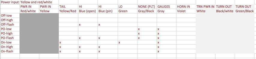
Excited that I managed to take care of this question myself.
Still curious about the grounding of the horn, though. I am going to wire it so power enters the horn then exits to the switch, where when pressed, it should ground and complete the circuit. This is assuming the switch can just ground at the bar, which seems weird but the only possible way to wire it...there is only one lead in and no lead out from the horn button. And it worked before, so soldering a lead on would seem to be unnecessary.
(And here's the long story long, for those who care to read about my experiment:
I made a chart showing how all the possible switch positions give power to the various wires. I then hooked 9v battery positive power up to the wire I was testing as an input, and attached the negative lead from my multimeter to the 9v negative terminal. Then, I could test for 9v output at each wire which came off the switch. Put an "X" where I found voltage, and voila. Well, not quite voila...after wondering why no single wire gave me a useful output, I realized it was because I'd need to use multiple wires. The charts for red/white and yellow seemed to mesh well, so I gave them both power and came up with the chart.
Deduced the intended function of each wire based on which switch combo activates it, wrote it in on the chart, and I'm set!!)
 Topic: Switch schematic (Read 2657 times)